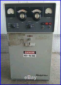
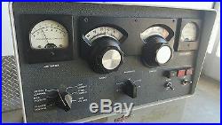
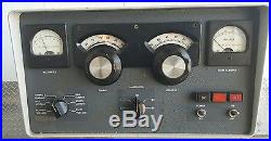
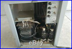
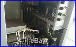
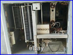
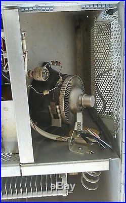
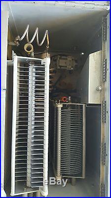
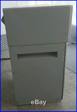
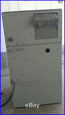
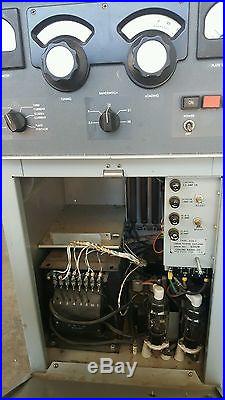
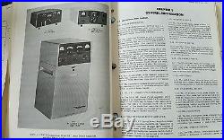

Up for sale is a very rare linear amplifier. The owner was a ham guy. This unit has been sitting for some time but was in his rig. I have powered on but not tested pass this point. The Collins 30S-1 Linear Amplifier features: RF INVERSE FEEDBACK for better linearity. INSTANT SWITCHING between low and full kilowatt power. QUICK AND ACCURATE TUNING, offering the amateur a bonus in ease of operation and optimum operating efficiency. AUTOMATIC LOAD CONTROL, assuring a clean signal. COOLING SYSTEM which operates quietly and efficiently. SIMPLE AND DIRECT CONNECTION between the 30S-1 and the exciter and station control unit. PROTECTIVE CIRCUITRY which protects tubes and other components from damage due to mistuning or malfunction. Requiring 70-100 watts driving power (supplied by the Collins 32S-3 Transmitter or KWM-2 Transceiver) the 30S-1 Linear Amplifier provides your SSB and CW station with the full legal power input for SSB (1 kw average) or 1 kw input for CW transmission. All the 30S-1 controls are easily accessible on the front panel. This front panel design allows you to tune the 30S-1 swiftly, surely and easily. With the push of a button you can switch instantly from the 100 watt power level of your S/Line transmitter to the full kilowatt output of the 30S-1; yet you retain high linearity and clean signal. The 30S-1 can also be tuned to frequencies outside of the amateur bands. Automatic Load Control voltage from the 30S-1 is fed back to the transmitter, assuring you of maximum talking power without over driving and distortion. Collins Automatic Load Control, in combination with Collins’ RF inverse feedback, is a major design feature in the 30S-I which gives you more talking power with a cleaner signal than any other linear amplifier in the amateur field. The 30S-1 is a completely self-contained, single tube, grounded grid linear amplifier. The tube used is the commercially popular Eimac 4CX1000A. Correct tuning and loading are indicated by a zero reading on a full scale multimeter. The loading control and PA tuning control are simply adjusted to obtain zero meter indication. 30S-1 SPECIFICATIONS MODE: SSB or CW. TYPE OF SERVICE: Attended operation SSB continuous; CW 50% duty cycle. POWER REQUIREMENTS: 115 v or 230 v, 50-60 cps, single phase, 2000 watts maximum. DRIVE POWER: 60-100 watts for full output. PLATE POWER INPUT: Nominal average, 1000 watts on SSB; 1000 watts on CW. POWER OUTPUT: 1000 watts PEP. FREQUENCY RANGE: 3.4-30.0 mc, covering 80, 40, 20, 15 and 10 meter amateur bands. By retuning input coils as necessary, the following general Coverage hands can be accommodated: FREQUENCY BAND TOTAL COVERAGE 3.5 mc 3.4- 5.0 mc 7.0 mc 6.5- 9.5 mc 14.0 mc 9.5-16.0 mc 21.0 mc 16.0-22.0 mc 28.0 mc 22.0-30.0 mc HARMONIC AND OTHER SPURIOUS RADIATION: Second harmonic -40 db; all others at least 50 db down. Third order distortion at 1000 watts PEP output 35 db below signal. NOISE LEVEL: 40 db below one tone Carrier. AMBIENT TEMPERATURE: 15 -45 C. AMBIENT HUMIDITY RANGE: 0%-90%. SIZE: 17″ W, 30-5/8″ H, 18-3/4 D. OUTPUT IMPEDANCE: Variable; 50 ohms nominal, unbalanced with not more than 2:1 SWR. 30S-1 CIRCUITRY The power amplifier stage is a single, ceramic tetrode which is cathode driven. The grid is grounded for r-f by capacitor C104. The screen grid is connected directly to ground. The plate power supply, the screen grid power supply, and the control grid bias supply are connected in series. The junction between the plate power supply and the screen grid power supply is grounded through the screen current meter shunt. This arrangement places the cathode at negative potential with respect to the screen grid. The bias supply is connected between the cathode and the control grid. INPUT CIRCUITS Pi-network broad-tuned circuits and the interconnecting r-f feed line match the 50-ohm input impedance to the cathode impedance, which is approximately 100 ohms. The 20.5-foot length of cable (furnished) is necessary between the 32S-1 (or KWM-2) driver and the 30S-1 input circuits. This is due to the necessity of having an even multiple of 180-degree phase shifts between driver plate and power amplifier grid. The cable length and the 30S-1 input circuits together accomplish this. An even multiple of 180-degree phase shifts is necessary because modulation components cause a change in the resistive PA cathode impedance which is translated to a shift in reactive impedance at the driver plate. The shift in reactive impedance, at the driver plate, results in phase modulation of the driver and increases the total over-all distortion of the system. A 2.5-foot additional length of cable is furnished to bring the total interconnecting cable length to 23.0 feet for use with the KWM-1 as a driver. Drive power required for maximum legal input on SSB is 80 watts PEP. OUTPUT CIRCUITS The plate circuit of the power amplifier is tuned by a pi network consisting of C120, L109, L104, C121, and C122. Capacitors C121 and C122 are ganged together and are adjustable by front panel control (LOADING) for matching the pi-network circuit to the impedance of the antenna and feed system in use. Capacitor C120 may be adjusted by the TUNING control on the front panel for resonating the tank circuit to the frequency in use. Output from the plate tank circuit is connected through the contacts of antenna changeover relay K101 to the antenna when the control circuits are switched to transmit function. POWER SUPPLY CIRCUITS Three d-c power supplies and three a-c filament supplies are included in the 30S-1. The power supply may be connected to 115-volt single-phase or to a 230-volt, three-wire, single- phase source. The 230-volt, three-wire connection is recommended. High-voltage plate transformer T201 has two primary windings. These windings are connected in parallel for 115-volt operation, and in series for 230-volt operation. The 12-volt a-c filament winding of the bias supply transformer supplies current for the filament of the alc rectifier, the pilot lamps in the two meters, and the pilot lamps which light the two dials. This transformer winding also supplies current for rectified d-c relay power. The bias winding of the transformer, T203, is connected to CR207 and CR208 in a full-wave rectifier circuit. This circuit provides grid bias voltage for the power amplifier. The heater of the 3-minute time-delay relay is supplied power from the 115-volt a-c connections which also furnish power to the high-voltage rectifier filament transformer, T202. The filament transformer, T103, supplies a-c power for the heater of the thermal over-load relay, K102. Taps on the primary of the high-voltage plate transformer, T201, are switched to provide the different voltages necessary for the power amplifier in CW or SSB operation. Power amplifier bias voltage is switched to one of two taps on the bias supply bleeder resistors for CW or SSB operation. The high-voltage screen supply rectifiers are eight, type 1N1492 silicon diodes in a full-wave bridge circuit. Each rectifier diode is paralleled with a 0.001-uf capacitor to protect it against high transient voltages. The high-voltage plate supply has a secondary winding from T201 and its high voltage is rectified by a pair of 3B28 rectifier tubes V201 and V202. SAFETY INTERLOCK CIRCUITS The top cover and the power supply front door operate safety interlock switches for operator protection. When the top cover is opened, interlock switch S103 breaks the circuit to the coil of the plate contactor, K203. This removes all high voltages from the 30S-1. When the power supply compartment (lower) door is opened, interlock switch S205 breaks the same circuit and removes all high voltages. Both interlock switches are mechanically interlocked with shorting switches which short out the high-voltage filter capacitors at the same time the interlock circuit opens. The r-f compartment interlock switch, S102, is mechanically ganged with shorting switch S101, and the power supply compartment interlock switch, S205, is mechanically ganged with shorting switch S206. This arrangement protects the operator from accidentally coming in contact with approximately 3000 volts d-c which is present in either compartment. TIME DELAY AND STEP-START CIRCUITS When POWER-OFF switch S202 is closed, the 115-volt a-c power is applied to the heater of the 3-minute time-delay relay, K202. After the power has been applied to its heater for approximately three minutes, the bimetallic contacts close. These contacts are in series with the interlock circuits and the coil of plate contactor K202. When the ON push button is depressed, K202 is energized, contacts of K202 close and apply power to the step-start relay, K201, through d-c rectifier CR205. The large electrolytic capacitor, across the coil terminals of K201, requires a fixed charging time to rise to a potential high enough to energize the relay. When this time has passed, K201 energizes and shorts out the step-start resistors. Until relay K201 has closed, all power applied to the transformer primary winding has been dropped through the two step-start resistors, R201 and R233. Thus, the high-voltage power supply starts at low primary voltage and, after the step-start cycle has elapsed, switches to full voltage. This allows time for partial charging of the large, high-voltage filter capacitors, C207 and C208, before the application of full secondary voltage to the rectifier plates. During this time, the rectifier tubes are protected from damaging high peak currents. THERMAL AND OVERLOAD CIRCUITS The thermal overload relay, K102, protects the power amplifier tube from over dissipation and loss of cooling air. Its bimetallic strip has contacts connected in series with the interlock system. The thermal overload switch is located in the air stream from V101. Current from transformer T103 is passed through the heater of K102. This current keeps K102 temperature just below that necessary to open its contacts. If the air stream fails, the temperature of the bimetallic strip increases, opening the interlock circuit, and removing voltages from the power amplifier. If over-dissipation occurs in the plate of the power amplifier, the higher air temperature causes K102 to operate and break the interlock circuit. POWER CONTROL CIRCUITS When the POWER-OFF switch is operated to POWER position, 115-volt a-c power is applied to the filament and control circuits. If the 3-minute time delay of K202 has passed, and if all interlock circuits are in proper operating condition, the plate contactor may be energized by pushing ON switch S203. When K203 contacts close, one set of them holds the electrical connection to the coil and keeps the relay closed after the ON push button is released. Other contacts of K203 supply power to the antenna changeover relay circuit and to the primary winding of the high-voltage transformer, T201. Power to T201 is applied from K203 contacts through two step-start resistors. These resistors reduce the voltage applied to the transformer until capacitor C203 charges high enough that the voltage across it will energize step-start relay K201. When K201 closes, its contacts short out the step-start resistors and allow full voltage to be applied to the transformer winding. The modulation envelope is detected by power amplifier grid rectification. This signal is filtered of r-f by L108 and C140 and applied through transformer T102 to the alc rectifier, V203. The audio signal is rectified by V203 to produce a negative control voltage which is a function of the modulation level. The alc rectifier, V203, is connected as a voltage doubler. The negative control voltage produced by the alc rectifier is fed back to the alc line of the exciter to produce approximately 3 db of override control. The resistor, R234, in series with V203 filament, reduces the no-signal d-c level on the alc line. This no-signal d-c level is caused by the tube contact potential. If not reduced, it might cause a delay voltage to be present on the exciter alc bus. The 3 db of alc override control produced in the 30S-1 reduces the exciter r-f gain and keeps the drive level within tolerable limits. Automatic load control helps to keep the drive level low enough to prevent driving the power amplifier into distortion. This feedback is accomplished by capacitor C103, which couples some of the plate energy back to the grid circuit. Although there is no phase inversion between the cathode and the plate circuits of a cathode- driven amplifier, there is a phase inversion between the cathode and the grid circuit, providing the grid is not bypassed completely at the r-f frequency. Therefore, the feedback voltage is out of phase with the grid voltage. Capacitors C103 and C104 form a voltage divider circuit to maintain the proper amount of feedback voltage. TUNING & LOADING METER CIRCUIT One section of the SSB-CW switch, S201, selects the proper output voltage from the tuning and loading bridge circuit for the TUNING & LOADING meter indication. This circuit and the power amplifier tube form a specialized vacuum-tube voltmeter bridge circuit. It consists of V101, CR101A, and CR101B, and the associated load resistors and filter networks. The bridge is balanced when the plate circuit TUNING and LOADING controls are set to present the proper load impedance to the power amplifier plate. The meter then will read zero, and the power amplifier tube will be operating at the proper gain level for maximum efficiency and linearity. The item “Rare Collins 30S-1 HF Ham Linear Amplifier works great with the Collins Receiver” is in sale since Saturday, July 30, 2016. This item is in the category “Consumer Electronics\Radio Communication\Ham, Amateur Radio\Ham Radio Transceivers”. The seller is “the_vintage_gear_guys” and is located in Roseville, California. This item can’t be shipped, the buyer must pick up the item.

Incoming search terms:
- collins 30 s 1 for sale
- collins 30 s1 for sale
- collins 30s1 for sLE
